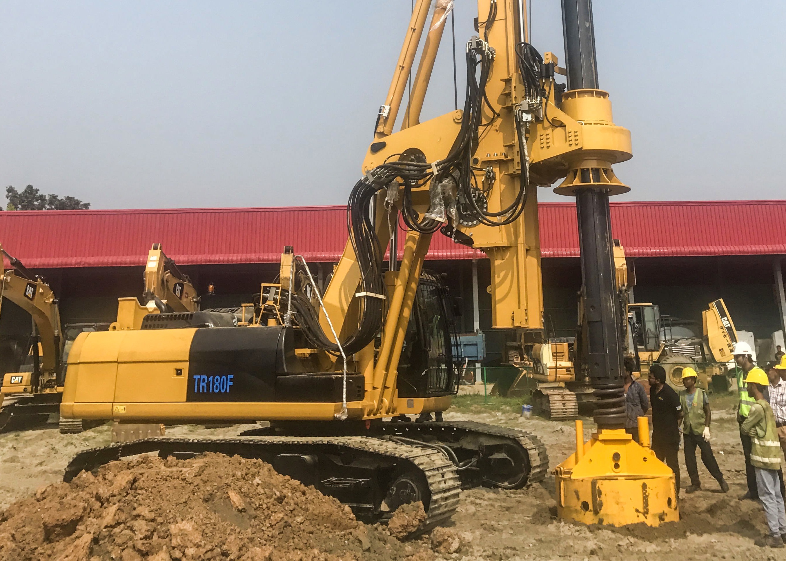
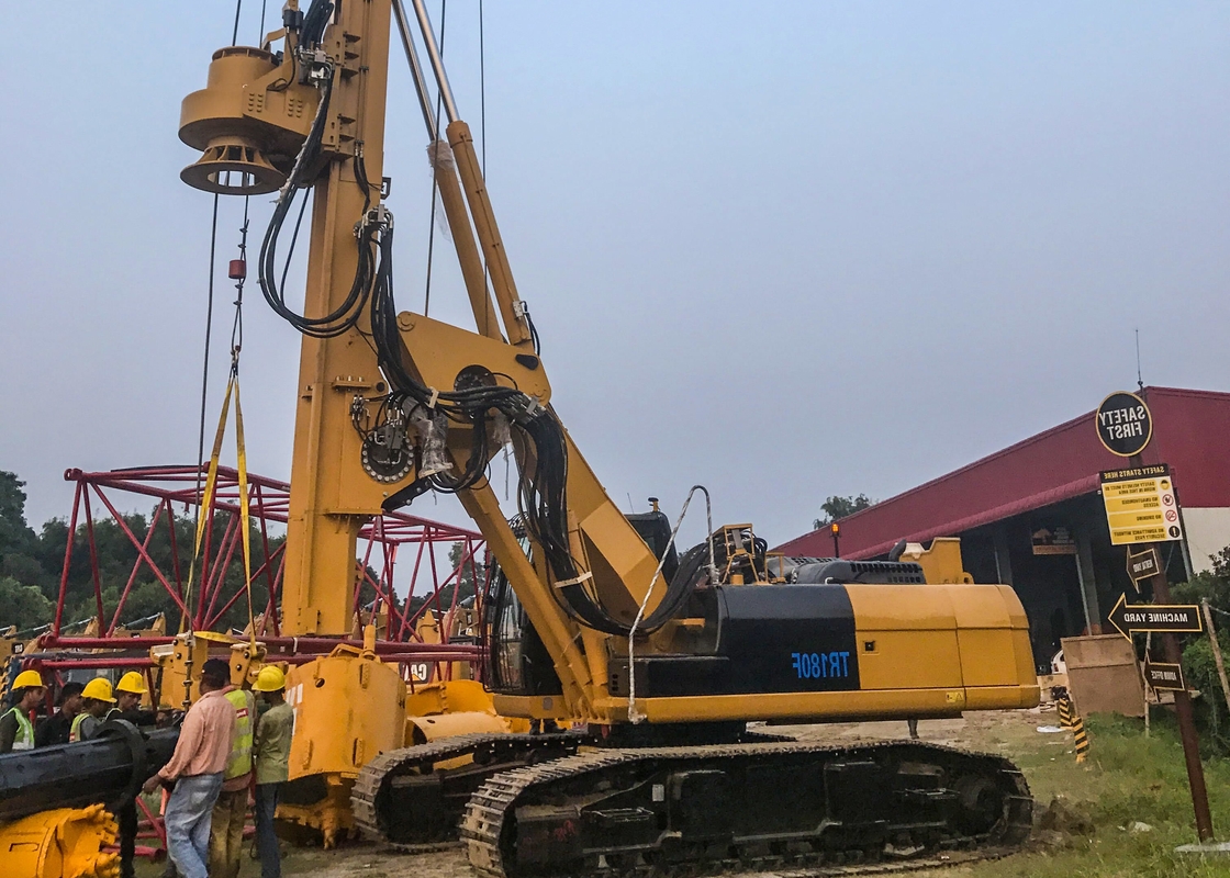
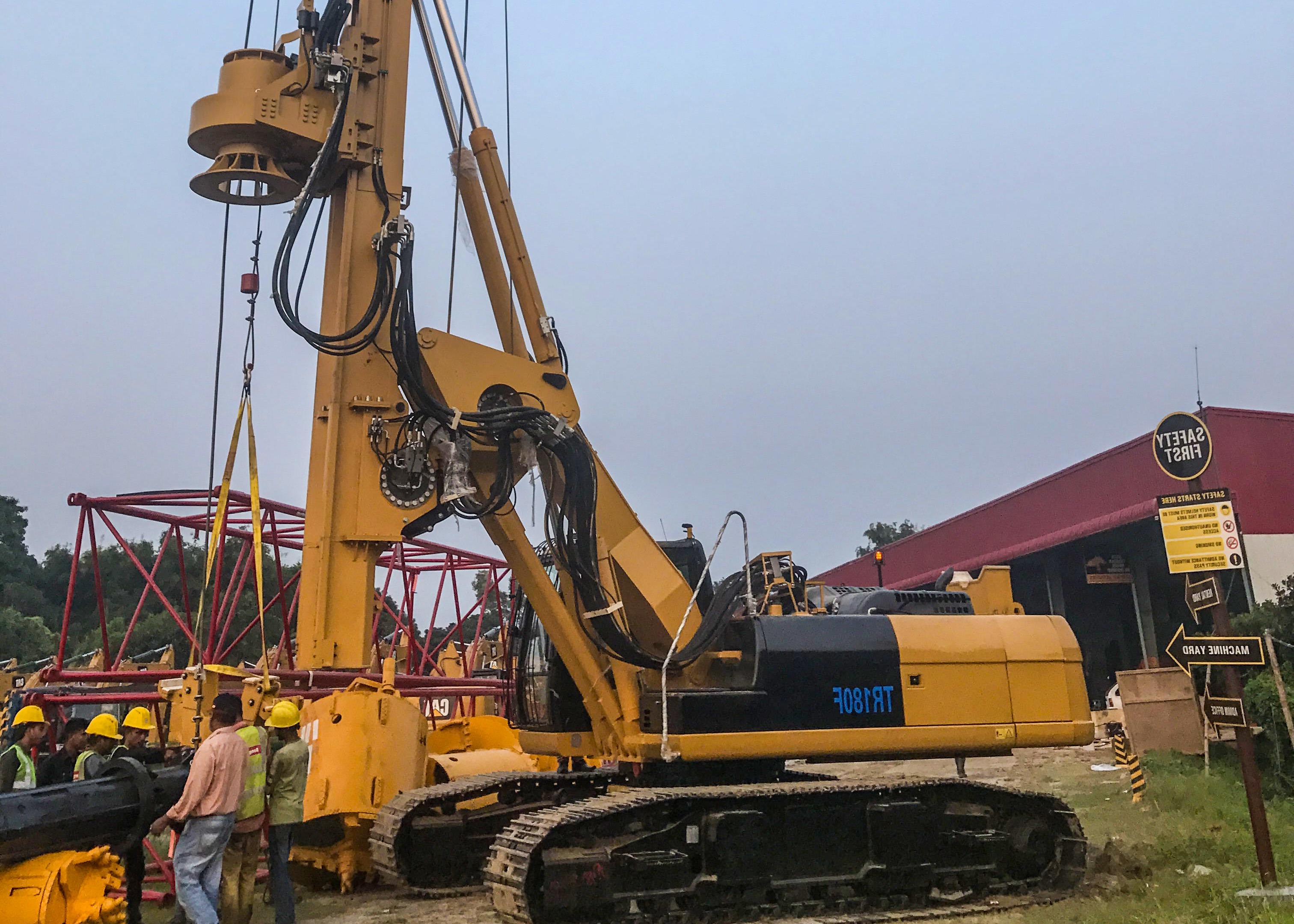
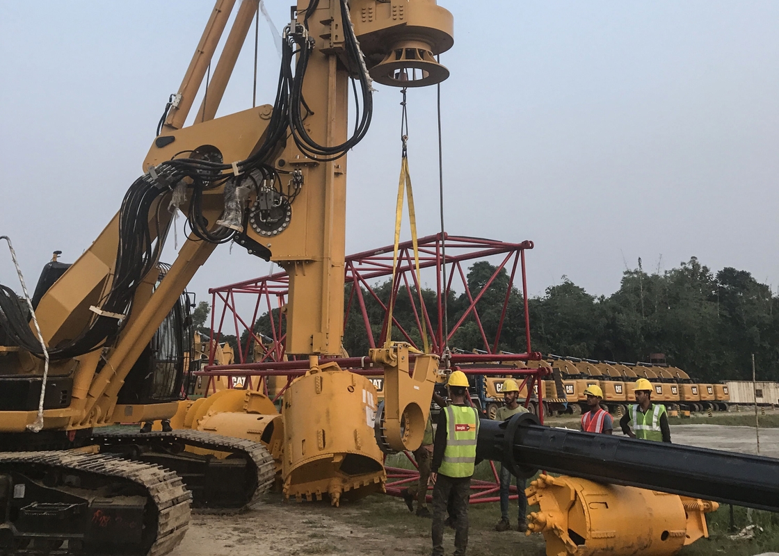
Application Scope of TR180F Drilling Rig:
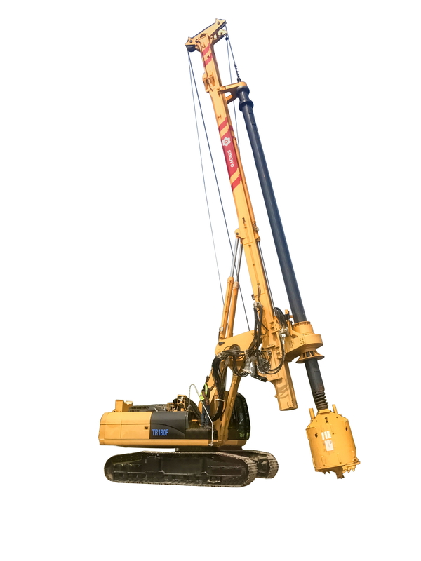
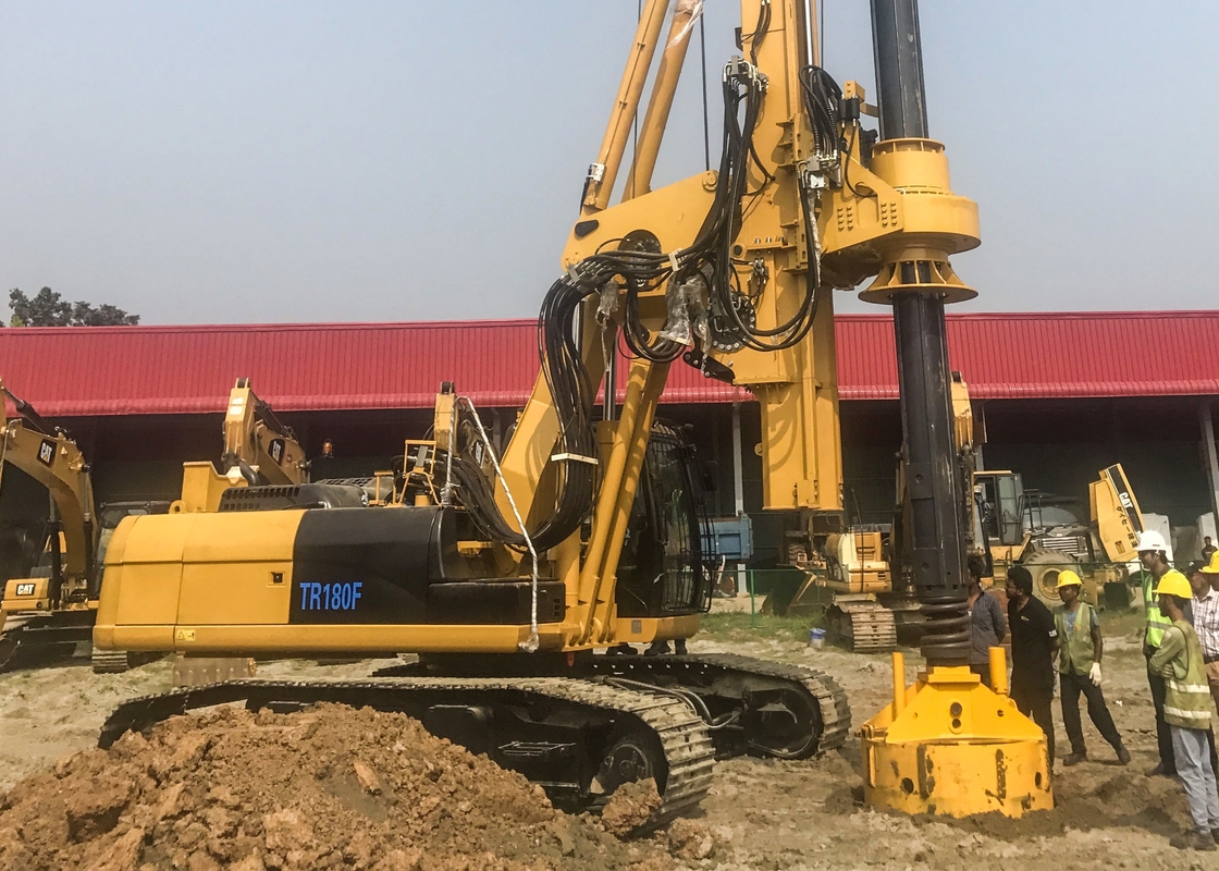
The TR180F rotary drilling rig is one kind of soil-bored cast-in-place pile construction machinery, which fulfills the periodic operation cycles by driving the rotary bucket via kelly bar to cut the soil and then lifting out of the pile hole for soil dump.
TR180F rotary drilling rig is mainly available for the construction of industrial and civil buildings, bridge, etc., and is only applicable for the drilling with kelly bar equipment. Do not use other drilling equipment.
Introduction of drilling rig structure and functions:


1. Undercarriage
It provides the power source to the drilling rig and fulfills the traveling of complete machine, swing of actuating mechanism, and movement of complete machine.
2. Boom
It connects the up-carriage and triangular mechanism and its rotation can adjust the spacing between the mast and the rotation center.
3. Luffing cylinder
It control s the rotation angle of boom.
4. Support rod
It rotates synchronously with the boom to ensure parallel of triangular mechanism to the up-carriage.
5. Lower mast
It’s functioned for the guidance and lower limit of the power unit.
6. Triangular mechanism
It connects the mast and boom as well as support rod and luffing cylinder.
7. Main winch
It lifts and lowers the kelly bar via wire rope.
8. Auxiliary winch
It lifts the auxiliary tools such as pile casing via wire rope and is one auxiliary lifting mechanism for the drilling rig.
9. Mast cylinder
It adjusts the angle of mast.
10. Middle mast
It’s functioned for the guidance of kelly bar and power unit.
11. Upper mas
It is functioned for the guidance of kelly bar.
12. Cathead
It’s fitted with wire rope guide pulley to support and guide the wire rope.
13. Servo frame
It is functioned for the guidance of kelly bar and the installation of swing support fort the kelly bar.
14. Kelly bar
The telescoping kelly bar transmits the torque and pressure of the power unit to the drill bucket and its length determines the drilling depth.
15. Pressing cylinder
It provides the drilling pressure and lifting force for the power unit.
16. Power unit
It provides drilling torque to the kelly bar and drilling tool.
17. Drilling bucket
It is used to load the slag drilled.
Technical Specification:
|
Technical specification for TR180F rotary drilling rig
|
|
Item
|
Parameter
|
Item
|
Parameter
|
|
Maximum output torque
|
220KN.m
|
Traction force
|
42T
|
|
Maximum drilling diameter
|
1800mm
|
Undercarriage model
|
CAT330D
|
|
Maximum drilling depth
|
60000mm
|
Track width
|
800mm
|
|
Rotary speed
|
6-27rpm
|
Undercarriage extension width
|
4300
|
|
Maximum crowd force
|
170KN
|
Overall dimensions of machine under transport status
|
14250X3000X3273
|
|
Maximum lifting force
|
190KN
|
Engine manufacturer
|
Caterpillar
|
|
stroke of crowd system
|
4500mm
|
Engine mode
|
C7 electronic injection turbocharged engine
|
|
Left/right tilting angle of mast
|
6°
|
Maximum lifting force of auxiliary winch
|
110KN
|
|
Forward inclination of mast
|
5°
|
Rope diameter of auxiliary winch
|
18mm
|
|
Engine power
|
187KW
|
Maximum lifting speed of auxiliary winch
|
75m/min
|
|
Rope diameter of main winch
|
26mm
|
Swing speed
|
4-6rpm
|
|
Maximum lifting force of main winch
|
200KN
|
Total weight, including standard kelly bar
|
60.6T
|
|
Maximum lifting speed of main winch
|
76m/min
|
Construction of Drilling Rig:
1. Construction preparations
a. Inject the lubricating grease to all lubricating points. Check the hydraulic oil level and quality. Check the gear oil level and quality for winches, power unit, and up-carriage swing reducer. Check the engine oil level and quality of engine. Check the filter for necessity of replacement. Check the drilling teeth for necessity of replacement. Check the drilling bucket for normal opening and closing.
b. Verify the geological report of the stratum. Depending on the stratigraphic distribution (such as cement hardened layer, miscellaneous fill, clay, fine sand, medium-coarse sand, gravel, and intermediately weathered sandstone), choose appropriate drill tool as per stratum and establish construction scheme for construction.
c. Choose the drilling tool:
Determine the diameter of drilling tool in accordance with the requirements of the construction drawing. Generally, the diameter of the drilling tool is smaller than the specified diameter of the hole by 1cm~2cm. Ensure there is free of excessive interference coefficient. During the drilling, it's appropriate to choose short auger drilling tool for cement hardened layer. Choose special drilling bucket drilling tool for sand and gravel layers. When the drilling bucket can't drill in the intermediately weathered hard layer, choose short auger drilling tool for crushing and then dredge the drilling slag with drilling bucket. (Please refer to the relevant descriptions in Chapter VII for the detailed choice method of drilling tool).
2. Positioning of drilling rig
Ensure the levelness in the vicinity of the pile position, drive the tracks of the drilling to near the pile position, and align the tip of the auger drilling tool to the marked point of pile position.
When the drilling rig is stopped and the swing center is 3.1m-3.5m from the hole, whenever possible, operate the luffing cylinder to retract the mast to as minimum as possible from the swing center, in order to reduce the influence of the alternate tension on the hole position during the lifting and lowering of the drilling rig. Check for presence of obstacle within the swing radius.
3.Construction of drilling rig
Collaring
After crushing the hardened layer, operate the main winch lever to lift the drilling tool to be off the hole opening for a distance and then stop. Operate the up-carriage swing switch to swing the machine and stop at the soil dump position. Press the rapid rotation switch on the power unit rotation lever and operate the lever to rotate the power unit at high speed for slag ejection. After crushing the hardened layer, remove the short auger drilling tool and replace with conventional drilling bucket and reamer for drilling. After a depth enough for the pile casing is reached, use auxiliary winch to lift the pile casing and install into the hole. Then, use the theodolite and joint spider to verify whether the pile position is consistent with the center of the pile casing. If inconsistent, move the pile casing for correction. After the correction, fill the periphery of the pile casing with soil. The embedment of the pile casing is completed.
Drilling
The drilling operation can be conducted after the pile casing is embedded.
While operating the power unit for drilling rotation, lower the drilling pipe to the bottom of the hole and press the main winch floating button for pressed drilling. When the drilling slag reaches certain bucket amount (The bucket amount depends on the geological condition), the drilling tool can be lifted.
To lift the drilling tool, rotate the kelly bar reversely for 2~5 turns to close the gate of drilling bucket. While lifting the power unit, operate the main winch to lift the kelly bar and drilling tool off the hole opening, rotate the up-carriage along with the kelly bar to the soil dump position, and lift the kelly bar and strike open the bucket gate to dump the drilling slag. Rotate the power unit to close the bucket gate. Rotate the up-carriage to the pile position, reset the rotation angle to zero via touchscreen, and continue the next cycle. Repeat the above cycles, till the design hole depth is drilled.

Daily Maintenance:
During drilling, the following maintenance should be done at any time.
1. Before operation each shift, add grease to the Kelly bar elevator (Kelly bar swing connector);
Caution: While adding grease to the grease nipple of elevator, be sure to discharge all dirt containing tiny sand from the connections, which will otherwise wear the bearing, thereby reducing the sensitivity of the elevator.
2. Check the slewing bearing for flexible rotation before the operations of each work shift, and add lubricating grease to the follow-up carrier pivotal bearing every week;
3. Frequently check the intactness of wire ropes;
4. Frequently check the damages of oil pipes and seal rings, and in case of damage, replace in a timely manner.
5. Frequently check the circuit relays for presence of aging, and prepare the spare parts timely;
6. Check the bearings of kelly bar elevator (kelly bar swing connector) for flexible rotation, and immediately replace any damage bearing;
7. Frequently check the bolts and hinges if there is any wear, looseness, and breakage and immediately replace any damaged one.

 Your message must be between 20-3,000 characters!
 Please check your E-mail!
  Your message must be between 20-3,000 characters!
 Please check your E-mail!

